- All
- Product Name
- Product Keyword
- Product Model
- Product Summary
- Product Description
- Multi Field Search
Views: 0 Author: Site Editor Publish Time: 2026-08-09 Origin: Site


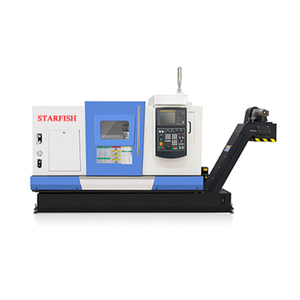
I still remember the first time a customer sent us back a batch of rejected parts. The material was 42CrMo steel, the machine was one of our CK6 series horizontal lathes, and the problem? Dimensional inconsistency across the batch. After two days of back-and-forth, we traced it to something embarrassingly simple — the operator had been running the spindle at 600 RPM when the recommended range was 350-450 RPM for that specific material and insert grade.
That was probably 12 years ago, but the lesson stuck. Cutting speed — the single most influential parameter in any turning operation — is also the one most shops get wrong. Not because they don't know the theory. They do. But in practice, operators push speeds higher to save time, or drop them lower "to be safe," without understanding the actual consequences.
We started documenting this systematically about five years ago. Every time a customer reported tool life issues, surface finish problems, or dimensional drift, we logged the cutting parameters they were running. Over 200 tests later, I want to share what the data actually shows — because some of it surprised even us.
If you studied machining in school, you probably remember the Taylor tool life equation: V×Tn = C. Cutting speed multiplied by tool life to some power equals a constant. It looks clean on a whiteboard. What most people don't realize is how aggressively tool life deteriorates when you increase speed beyond the recommended range.
Here's a real example from our test shop. We ran P25 carbide inserts on AISI 1045 steel (a material we machine constantly) at three different cutting speeds:
At 180 m/min (within recommended range): insert lasted 45 minutes of continuous cutting before flank wear hit 0.3mm
At 220 m/min (20% above recommended): insert lasted 22 minutes — less than half
At 260 m/min (45% above recommended): insert lasted 9 minutes
That's not a linear relationship. A 45% increase in speed gave you a 5x reduction in tool life. The math checks out with Taylor's exponent (n ≈ 0.25 for coated carbide on medium carbon steel), but seeing it in person still makes you think twice about cranking up the RPM.
We've seen this pattern repeat across dozens of materials. The tool life penalty for running too fast is always exponential, not linear. That $15 insert you save time on? You're burning through 5x more of them. And that's before you factor in the scrap risk.
Here's what catches people off guard. We tend to assume that running slower is the "conservative" choice — safer for the tool, safer for the part. It isn't.
When cutting speed drops below the recommended range, three things happen that most operators don't anticipate:
First, built-up edge (BUE) forms rapidly. At low speeds, the chip-tool interface temperature stays in a range where the workpiece material welds to the insert edge. We've examined inserts after low-speed cutting on stainless steel, and the amount of material adhesion is alarming. It changes the effective geometry of the cutting edge, destroys surface finish, and when the BUE finally breaks off (as it inevitably does), it takes carbide with it.
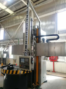
Second, you get work hardening on susceptible materials. This is especially bad on austenitic stainless steels (304, 316), nickel alloys, and certain titanium grades. The insert rubs instead of shearing, and the surface layer hardens. The next pass then cuts into hardened material, which accelerates wear dramatically. We once had a customer machining 316L on a vertical lathe — our CK5 series vertical lathes are well-suited for the large flanges they produce — and they were running at 60 m/min on a material that needs at least 120 m/min to avoid the work-hardening zone. The first pass was fine. The second pass ruined the part.
Third, cutting forces actually increase at very low speeds. Counterintuitive, right? But at low speeds, the shear zone shifts, the chip doesn't flow cleanly over the rake face, and you get higher mechanical loading on the insert edge. This leads to chipping — not the gradual flank wear you expect, but sudden edge failure.
Here's something I wish more programmers understood. Cutting speed and feed rate don't operate independently. Change one, and the optimal range for the other shifts too.
We discovered this during a troubleshooting visit to a factory in Turkey. They were machining AISI 4140 shafts on a CK6163 horizontal lathe, and they were getting inconsistent surface finish — Ra values bouncing between 1.6 and 3.2 μm on the same part. The cutting speed was correct (200 m/min), the insert was right (CNMG 120408 with PVD coating), but the feed rate was 0.15 mm/rev — too low for that nose radius and cutting speed combination.
The problem was that at 0.15 mm/rev with a 0.8mm nose radius, the theoretical surface roughness (calculated as f²/8r) was only 0.28 μm. But the actual roughness was 4-10x worse than theory. Why? Because the feed was so low that the insert was rubbing through a significant portion of the cut, creating thermal and mechanical instability. The cutting edge was in contact with the workpiece for too long per revolution, generating heat that softened the insert's edge and caused micro-plastic deformation.
We bumped the feed to 0.3 mm/rev and the roughness immediately settled to 1.2-1.6 μm. The insert lasted 40% longer too. The theoretical roughness went up to 1.1 μm, but the actual finish was better because the cutting mechanics were stable.
That's the kind of thing you only learn from watching chips fly — not from a textbook. The optimal feed rate depends on cutting speed, nose radius, material, and even the machine's rigidity. A heavier machine like our CK6180 can handle higher feeds at the same speed than a lighter machine because the damping is better.
Of the three primary cutting parameters — speed, feed, and depth of cut — depth of cut (DoC) is the least discussed. It has the smallest effect on tool life (Taylor's exponent for DoC is roughly half that of feed rate). But get it wrong, and the consequences are immediate and sometimes dangerous.
The main issue we see is interrupted cuts with insufficient DoC. When you're turning a casting or a forging with a scale layer, and your DoC is smaller than the scale depth, the insert enters and exits the hardened scale zone on every revolution. This creates a thermal-mechanical fatigue cycle that cracks the carbide edge in a matter of minutes.
We had this exact problem with a customer machining pump casings. The material was high-silicon aluminum alloy (A390), and the castings had a 0.5mm hard skin. They were taking a finishing pass at 0.3mm DoC — right at the boundary. Half the time the insert was in the skin, half the time it wasn't. Insert life was unpredictably short, sometimes lasting one part, sometimes three.
The fix was simple once we understood it: either take a 0.8mm DoC to fully penetrate the skin in one pass, or add a separate roughing pass at 1.5mm DoC to remove the skin before finishing. They chose the two-pass approach, and insert life went from "unpredictable" to a consistent 120 parts per edge.
For finish turning on clean bar stock, we typically recommend 0.3-0.8mm DoC depending on the material and required tolerance. For roughing, we go 2-5mm — but always deep enough to get past any surface irregularities in a single pass.
After years of testing, we've built an internal reference for cutting speed ranges. These aren't from insert manufacturer catalogs — they're from our actual experience shipping machines and helping customers optimize their processes across different materials. The ranges below are for coated carbide inserts (PVD or CVD) on rigid CNC lathes with adequate spindle power:
Material | Recommended Vc (m/min) | Notes |
|---|---|---|
AISI 1045 / S45C | 150-250 | Very forgiving. Most shops run 180-220 |
AISI 4140 / 42CrMo | 120-180 | Quenched & tempered: drop to 80-120 |
AISI 304 / 316 Stainless | 100-180 | Never below 80 — work hardening risk |
Cast Iron (GG25/GGG50) | 200-350 | High speeds work well. Watch for dust |
Aluminum (6061/A356) | 300-600+ | Uncoated carbide or PCD. High speeds OK |
Titanium (Ti6Al4V) | 40-80 | Low speed, high feed. Don't stop mid-cut |
One thing I want to emphasize: these ranges assume the machine can maintain consistent spindle speed under load. On smaller lathes with lower-power spindles, you may need to drop speeds 10-20% because the spindle can't maintain RPM when the cut gets heavy. We've tested this extensively — a CK6140 with a 5.5kW spindle will behave differently than a CK61100 with 30kW when you're taking a 3mm DoC cut on 4140.
Here's something that insert manufacturers conveniently leave out of their data sheets: the recommended cutting speeds assume a certain level of machine rigidity. In the real world, machine condition varies enormously.
We once helped a workshop in Vietnam troubleshoot terrible insert life on their old manual lathe that they'd retrofitted with CNC. The insert was a standard CNMG for steel, the material was mild steel (SS400), and they were running at 160 m/min — dead in the middle of the recommended range. But insert life was only about 15 minutes instead of the expected 40+.
The problem was the spindle bearings. They were worn, and under cutting load, the spindle was deflecting 0.02-0.03mm. That deflection created a varying chip thickness — sometimes thick, sometimes thin — which put the insert through constant shock loading. It wasn't a cutting speed problem. It was a machine problem masquerading as a cutting speed problem.
After replacing the spindle bearings, insert life jumped to 50+ minutes at the same speed. We've seen similar issues at least a dozen times. Before you blame the cutting parameters, check the machine. Specifically:
Spindle runout (should be under 0.01mm at the nose)
Bed way condition (wear creates vibration at certain positions)
Tailstock alignment (if you're using it — misalignment creates inconsistent DoC)
Tool holder condition (worn VDI/BMT interfaces introduce play)
If you're evaluating new equipment and comparing quotes, pay attention to spindle bearing specs and bed construction. A heavier machine with preloaded angular contact bearings will hold tighter parameters at higher speeds than a lightweight machine with standard deep groove bearings. That's why our vertical turning centers use paired angular contact bearings in the spindle — it's not just a spec sheet number, it directly affects what cutting parameters you can reliably hold.
I want to share one more example because it illustrates how much money is sitting on the table when cutting parameters aren't optimized.
A factory in Indonesia was producing about 2,000 shafts per month from AISI 1045 bars on a horizontal lathe. Their cycle time was 8 minutes per part. They were using standard PVD-coated inserts at 200 m/min, 0.3mm/rev feed, and 2mm DoC for roughing. Insert consumption was about 3 edges per hour — high, but they'd accepted it as normal.
When our applications engineer reviewed their setup, he noticed two things. First, their roughing DoC was only 2mm, and the bar stock had a 0.4mm mill scale. Half the time, the insert was partially in the scale, causing accelerated and unpredictable wear. Second, their finishing speed of 200 m/min was actually too high for the 0.15mm/rev finish feed they were using — the low feed combined with high speed was creating BUE on the insert nose.
We recommended three changes:
Added a skin-removal pass at 3mm DoC before the main roughing pass
Dropped finishing speed from 200 to 160 m/min and increased feed from 0.15 to 0.25 mm/rev
Kept roughing speed at 200 m/min but increased feed from 0.3 to 0.4 mm/rev
The results: cycle time went from 8 minutes to 7.5 minutes (actually faster, despite more conservative finishing parameters, because the roughing was more aggressive and consistent). Insert consumption dropped from 3 edges per hour to 1.8 edges per hour. At their insert cost and monthly production, the annual savings came to roughly $18,000 — just from parameter optimization, no new tooling required.
The interesting part? Their operators were experienced machinists with 10+ years each. They just hadn't been taught to think about the interaction between all three parameters and the machine's actual behavior. That's not their fault — it's an industry problem.
Here's what I recommend to every customer who buys a machine from us. Don't just take the insert manufacturer's recommended speed range and pick the middle. Run a mini Taylor test:
Take one bar of your most common material. Machine 5 test pieces at different speeds — say, 80%, 90%, 100%, 110%, and 120% of the catalog recommendation. For each piece, record:
Time to reach 0.2mm flank wear (use a magnifier or tool microscope)
Surface roughness at the start and end of each piece
Any unusual chip colors or shapes
Dimensional deviation from the programmed size
This takes about 2-3 hours and gives you actual data for your specific machine-material-insert combination. I've never seen a shop do this and not find a better speed range than what they were using.
We keep copies of these test results for every customer who asks, and over the years, we've built quite a database. If you're sourcing a CNC horizontal lathe or vertical turning center from us and want cutting data for your specific application, just ask. That's the kind of support that separates a real manufacturing partner from a box shipper.