- All
- Product Name
- Product Keyword
- Product Model
- Product Summary
- Product Description
- Multi Field Search
Views: 0 Author: Site Editor Publish Time: 2026-08-01 Origin: Site


Coolant systems and lubrication management represent one of the most underappreciated factors in CNC lathe performance. While most buyers focus on spindle power, axis travel, and control systems when evaluating machines, experienced machinists know that the coolant system directly determines whether a machine achieves its full potential in tool life, surface finish, and production consistency. A well-designed coolant system can extend tool life by up to 300%, reduce cycle times by 25%, and deliver surface finishes that would otherwise be impossible.
For procurement managers and workshop owners investing in CNC vertical lathes or CNC horizontal lathes, understanding coolant technology is not optional—it is essential for making informed purchasing decisions and controlling operational costs. The CK5 vertical lathe series and CK6 horizontal lathe models support a range of coolant configurations, from basic flood systems to high-pressure through-spindle delivery. This guide covers everything you need to know about selecting, operating, and maintaining coolant and lubrication systems on CNC lathes, with practical data to help you source from China manufacturers.
Modern CNC lathes employ several types of coolant delivery systems, each optimized for specific machining conditions. Understanding these options helps buyers specify the right configuration when requesting a quotation from a CNC lathe manufacturer.
Flood coolant is the standard delivery method in most CNC turning operations. Coolant is pumped from a reservoir through nozzles positioned near the cutting zone, flooding the tool-workpiece interface. This method works well for general-purpose turning, facing, and boring operations on most materials.
Flow rate: 10–25 liters per minute (L/min) for standard applications
Pressure: 2–5 bar typical
Best for: Steel, cast iron, aluminum general turning
Cost range: $1,500–$4,000 (included in base machine price)
MQL systems deliver an extremely small volume of lubricant—typically 5–50 milliliters per hour—as an aerosol mist directly to the cutting zone. This approach eliminates the need for large coolant reservoirs, pumps, and filtration systems, reducing both initial investment and ongoing maintenance.
Flow rate: 5–50 mL/hour
Pressure: 2–6 bar air carrier
Best for: Aluminum machining, cast iron turning, environmentally sensitive operations
Cost range: $2,000–$6,000 as an add-on option
Key advantage: Eliminates coolant disposal costs ($500–$2,000 per disposal)
High-pressure coolant systems deliver coolant at 20–150 bar directly into the cutting zone through specialized nozzles or through the tool body. The high pressure penetrates the chip-tool interface, providing superior cooling and chip breaking—especially critical when machining difficult materials like stainless steel, titanium, or Inconel.
Flow rate: 10–50 L/min
Pressure: 20–150 bar
Best for: Stainless steel, heat-resistant alloys, deep hole drilling, interrupted cuts
Cost range: $8,000–$25,000 as an option
ROI: Tool life improvement of 200–400% in difficult materials
Through-tool (through-spindle) coolant delivers pressurized coolant directly through internal channels in the tool holder and cutting tool, exiting at the cutting edge. This method ensures coolant reaches the exact point of cut, even in deep cavities and boring operations where external nozzles cannot penetrate.
Pressure: 20–70 bar typical
Best for: Deep hole boring, gun drilling, internal turning with long overhangs
Key advantage: 50–80% improvement in chip evacuation in deep boring operations
When ordering a CNC vertical turning center from a China manufacturer, always confirm whether the coolant system is included in the base price or quoted as an optional configuration. Many manufacturers offer coolant system upgrades that provide substantial returns through extended tool life and reduced downtime.
Selecting the correct coolant type for your workpiece material and machining operation is the single most impactful decision in coolant management. The wrong coolant choice can reduce tool life by 60% and produce unacceptable surface finishes.
Workpiece Material | Recommended Coolant Type | Concentration | Key Consideration |
|---|---|---|---|
Carbon Steel (P20-P40) | Semi-synthetic emulsion | 8–12% | Good lubricity for moderate speeds |
Stainless Steel (M10-M30) | Full synthetic + EP additives | 10–15% | High pressure required, chlorine-free EP |
Cast Iron (K10-K30) | Semi-synthetic or MQL | 5–8% | Cast iron generates fine dust, filtration critical |
Aluminum Alloys (N10-N30) | Emulsion or MQL with kerosene base | 5–10% or neat MQL | Prevent built-up edge, avoid alkaline pH >9 |
Titanium Alloys (S10-S30) | Full synthetic with high-flow flood | 10–14% | High pressure essential, minimize thermal shock |
Copper Alloys | Emulsion or semi-synthetic | 6–10% | Watch for staining, maintain pH 8.5–9.5 |
The table below shows the relationship between machining operation and coolant delivery requirements:
Operation | Coolant Priority | Recommended Pressure | Typical Flow Rate |
|---|---|---|---|
Rough Turning | Cooling + chip evacuation | 5–20 bar | 15–30 L/min |
Finish Turning | Surface finish quality | 3–10 bar | 10–20 L/min |
Deep Boring | Chip evacuation + cooling | 20–70 bar (through-tool) | 10–25 L/min |
Threading | Lubrication | 5–15 bar | 8–15 L/min |
Parting/Grooving | Penetration into narrow slot | 20–70 bar | 5–15 L/min |
Hard Turning (HRC >55) | Thermal shock prevention | 10–30 bar | 15–25 L/min |
Procurement tip: When requesting a quotation from a horizontal turning lathe supplier, specify your primary workpiece materials and operations. A knowledgeable manufacturer will recommend the appropriate coolant configuration, potentially saving you thousands of dollars in trial-and-error procurement.
Proper coolant concentration is the foundation of effective coolant management. Most CNC lathe coolant failures—premature bacterial growth, corrosion, skin irritation, and poor machining results—trace back to incorrect concentration levels.
Every CNC machine shop should own a handheld refractometer ($50–$200). This simple instrument measures coolant concentration in seconds by analyzing the refractive index of the coolant mixture. The reading is multiplied by the coolant's refractometer factor (provided by the coolant manufacturer, typically 1.0–2.5) to determine actual concentration.
The correct mixing sequence is critical. Always add concentrate to water, never water to concentrate. Adding water to concentrate creates an inverted emulsion that will never properly mix, resulting in poor lubrication, excessive foaming, and potential machine damage.
Step 1: Fill the reservoir with clean water to approximately 80% of final volume
Step 2: Slowly add the correct amount of coolant concentrate while agitating
Step 3: Top up with water to final volume
Step 4: Circulate the mixture for 15–30 minutes before use
Step 5: Check concentration with refractometer and adjust if needed
Check Frequency | Parameter | Acceptable Range | Action if Out of Range |
|---|---|---|---|
Daily | Concentration (refractometer) | ±2% of target | Add concentrate or water as needed |
Daily | pH level | 8.5–9.5 | Add biocide/pH adjuster if below 8.0 |
Weekly | Tramp oil content | <5% surface coverage | Skim or use oil separator |
Monthly | Bacterial count (dip slide) | <10^4 CFU/mL | Add biocide, increase concentration |
Quarterly | Full coolant analysis | Per manufacturer specs | Dump and recharge if degraded |
A disciplined maintenance program for coolant and lubrication systems prevents the three most expensive consequences of neglect: unplanned downtime, workpiece scrap, and premature tool wear. The following maintenance schedule applies to both CK5 vertical lathe and CK6 horizontal lathe installations.
Check coolant level in reservoir and top up with properly mixed coolant
Inspect nozzle positioning—nozzles must target the cutting edge, not the chip flow
Remove chips from coolant tank surface using a skimmer or magnetic separator
Check for unusual odors (sour smell indicates bacterial contamination)
Verify coolant pressure at the gauge matches the setpoint
Clean or replace chip conveyor filters and settle-out tank baffles
Test coolant concentration with refractometer and adjust
Check pH with test strips or meter
Skim tramp oil from coolant surface
Inspect coolant nozzles for blockage or wear
Clean the machine's coolant tank interior walls if biofilm is visible
Perform dip slide test for bacterial and fungal contamination
Clean the entire coolant system: flush lines, clean reservoir, inspect pump impeller
Check and clean coolant pump strainer
Inspect all hoses and fittings for leaks, cracks, or degradation
Clean or replace filtration elements (paper band, drum filter, centrifugal separator)
Complete coolant system flush and rebuild: dump old coolant, clean all surfaces, refill with fresh mixture
Inspect and service coolant pump (impeller, seals, motor bearings)
Calibrate concentration measuring instruments
Audit coolant piping for restrictions, leaks, or degraded sections
Review coolant type suitability—material mix changes may require coolant reformulation
Maintenance Item | Daily | Weekly | Monthly | Annual |
|---|---|---|---|---|
Coolant level check | ✓ | — | — | — |
Concentration test | ✓ | — | — | — |
pH test | ✓ | — | — | — |
Chip removal/skimming | ✓ | — | — | — |
Filter cleaning/replacement | — | ✓ | — | — |
Nozzle inspection | ✓ | ✓ | — | — |
Bacterial testing | — | — | ✓ | — |
System flush | — | — | — | ✓ |
Pump service | — | — | — | ✓ |
The relationship between coolant performance and tool life is well-documented in machining research. Proper coolant application can increase carbide tool life by 200–400% compared to dry machining, and HSS tool life improvements of 300–500% are common. The mechanism involves three simultaneous effects:
Cutting zone temperatures in CNC turning typically range from 600°C to 1,100°C depending on material and speed. Effective coolant reduces these temperatures by 200–400°C, slowing the diffusion wear mechanism that destroys carbide inserts. For CNC vertical lathe operations on large-diameter workpieces, where cutting speeds vary dramatically from center to edge, consistent coolant delivery becomes even more critical.
At the tool-chip interface, pressures reach 1–3 GPa. Coolant with appropriate extreme pressure (EP) additives forms a protective boundary film that prevents direct metal-to-metal contact, reducing crater wear and built-up edge formation.
Effective coolant flow breaks chips into manageable segments and flushes them away from the cutting zone. Long, stringy chips that are not properly evacuated can wrap around the workpiece or tool, causing surface damage, tool breakage, and scrapped parts.
Coolant Condition | Impact on Tool Life | Impact on Surface Finish | Productivity Impact |
|---|---|---|---|
Correct type and concentration | Baseline (100%) | Ra 0.8–1.6 µm achievable | Full rated productivity |
Low concentration (<5%) | -40 to -60% tool life | Ra degrades to 3.2+ µm | Reduced speeds required |
High concentration (>15%) | -10 to -20% (residue buildup) | Possible staining | Increased operating cost |
Bacterial contamination | -30 to -50% tool life | Inconsistent finish | Unplanned downtime for cleanup |
No coolant (dry cutting) | -70 to -90% tool life | Unacceptable for most finishes | Only viable for specific cast iron operations |
While the fundamental coolant chemistry is the same for both machine types, the physical arrangement of vertical and horizontal lathes creates different coolant management challenges that buyers should understand.
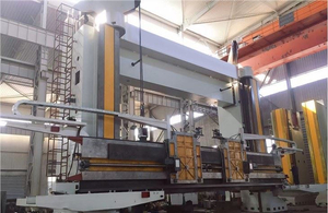
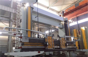
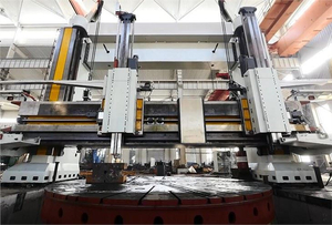
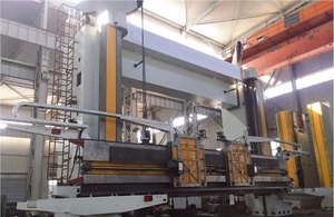
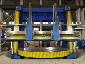
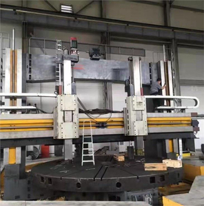
In a CNC vertical lathe, the workpiece rotates on a horizontal table and the cutting tool approaches from above or the side. Gravity assists chip evacuation downward into the chip conveyor, but coolant must be directed upward against gravity to reach the underside of large overhung features. The large table diameter (up to 6,300mm on CK5 models) requires multiple coolant nozzles positioned around the workpiece to ensure complete coverage.
Reservoir capacity: Typically 200–800 liters for CK5 series due to larger working envelope
Nozzle count: 3–6 nozzles recommended for large-diameter workpieces
Chip management: Gravity-assisted, but large chips from heavy cuts require robust conveyor design
The CK6 horizontal turning center arranges the workpiece between centers or in a chuck with the axis horizontal. Coolant delivery is more straightforward for external turning operations, but internal boring and deep hole drilling require careful nozzle positioning. Chip evacuation depends more heavily on coolant flow since chips fall along the bed way and can accumulate if flow is insufficient.
Reservoir capacity: Typically 100–400 liters for CK6 series
Nozzle count: 2–4 nozzles typical, positioned for front and rear tool stations
Chip management: Coolant flow critical for chip evacuation along bed ways
Feature | CK5 Vertical Lathe | CK6 Horizontal Lathe |
|---|---|---|
Typical reservoir size | 200–800 L | 100–400 L |
Recommended nozzle count | 3–6 | 2–4 |
Chip evacuation method | Gravity + coolant flush | Coolant flow dependent |
Coolant access challenge | Undercut features, lower workpiece zones | Deep boring, rear tool station |
Annual coolant cost | $3,000–$8,000 | $2,000–$5,000 |
Coolant disposal represents a significant and often overlooked operational cost. In many regions, spent coolant is classified as industrial waste requiring specialized disposal services. Understanding recycling options can reduce coolant-related costs by 40–60%.
Centrifugal separation: Removes fine particles and tramp oil, extending coolant life by 6–12 months. Equipment cost: $5,000–$20,000.
Vacuum distillation: Evaporates and recovers the water component, reducing waste volume by 90–95%. Equipment cost: $15,000–$50,000. Payback period: 12–24 months for shops with 3+ machines.
Ultrafiltration: Membrane-based separation that produces clean permeate water and a concentrated waste stream. Equipment cost: $10,000–$35,000.
Bioremediation: Uses specific bacteria to break down tramp oil and organic contaminants. Lower capital cost ($3,000–$8,000) but slower process.
Recycling Method | Capital Cost | Waste Volume Reduction | Payback Period | Best For |
|---|---|---|---|---|
Centrifugal separator | $5,000–$20,000 | Extends life 6–12 months | 6–12 months | All shops, basic maintenance |
Vacuum distillation | $15,000–$50,000 | 90–95% volume reduction | 12–24 months | Multi-machine shops |
Ultrafiltration | $10,000–$35,000 | 80–90% volume reduction | 12–18 months | High-volume production |
Bioremediation | $3,000–$8,000 | Extends life 3–6 months | 6–10 months | Small to medium shops |
Without recycling, typical annual coolant disposal costs for a CNC lathe operation include:
Small shop (1–3 machines): $1,500–$4,000/year in disposal fees
Medium shop (4–10 machines): $5,000–$15,000/year
Large shop (10+ machines): $15,000–$50,000/year
Even well-maintained coolant systems develop problems over time. The following diagnostic guide helps operators and maintenance teams identify and resolve the most common issues quickly, minimizing production impact.
Symptom | Probable Cause | Immediate Action | Preventive Measure |
|---|---|---|---|
Sour or rotten egg odor | Bacterial/fungal contamination | Add biocide, check concentration | Maintain concentration >8%, weekly dip slide |
Excessive foaming | High concentration, air leaks, wrong coolant type | Check concentration, inspect pump seals | Use defoamer sparingly, maintain correct mix ratio |
Machine corrosion (rust spots) | Low concentration, low pH, high chloride water | Increase concentration, add corrosion inhibitor | Use deionized water for mixing, maintain pH >8.5 |
Skin irritation on operators | High concentration, bacterial contamination, tramp oil | Check concentration, add skin-care additive | Provide gloves, maintain pH 8.5–9.5 |
Poor surface finish | Clogged nozzles, low flow rate, wrong coolant type | Clean nozzles, check pump pressure | Daily nozzle inspection, weekly pressure check |
Accelerated tool wear | Insufficient coolant at cutting zone, wrong concentration | Reposition nozzles, verify flow rate | Consider high-pressure or through-tool delivery |
Filter clogging (frequent) | Fine particle generation, filter rating too fine | Clean/replace filter, check chip size | Upgrade filtration system, optimize cutting parameters |
Coolant Milky/oily residue on machine | Tramp oil saturation, oil mist from mist coolant system | Skim tramp oil, check mist collector | Install oil skimmer, maintain mist collection system |
When procuring a CNC lathe from a China manufacturer, the coolant system configuration is often negotiable. Understanding your requirements before requesting a quotation ensures you receive the right system at a fair price.
Coolant type: Specify whether you need flood, MQL, or high-pressure coolant
Reservoir capacity: State your preference based on machine size and shift pattern
Filtration system: Paper band, drum filter, magnetic separator, or centrifugal
Coolant pump specifications: Flow rate (L/min) and pressure (bar)
Through-spindle coolant: Required for deep boring operations, specify pressure rating
Chip conveyor integration: Ensure coolant system and chip conveyor are compatible
Coolant brand compatibility: Confirm system materials are compatible with your preferred coolant brand
Upgrade Option | Typical Cost (USD) | Installation Time | Expected ROI Period |
|---|---|---|---|
High-pressure pump (20–70 bar) | $3,000–$8,000 | 1–2 days | 6–12 months |
Through-spindle coolant system | $5,000–$15,000 | 2–3 days | 8–18 months |
MQL system add-on | $2,000–$6,000 | 0.5–1 day | 3–8 months |
Upgraded filtration (centrifugal) | $5,000–$20,000 | 1–2 days | 6–12 months |
Coolant temperature chiller | $3,000–$12,000 | 1 day | 12–24 months |
Automated concentration monitoring | $2,000–$5,000 | 0.5 day | 6–12 months |
When evaluating quotations from competing suppliers, compare not just the machine base price but the total cost of the coolant system configuration that meets your production requirements. Some manufacturers include a basic coolant system in the base price, while others quote it separately. Always request a detailed breakdown.
Coolant systems and lubrication management are far more than maintenance afterthoughts—they are strategic investments that directly impact tool life, surface finish quality, production throughput, and total operating costs. Whether you are operating a CK5 vertical lathe for large-diameter workpieces or a CK6 horizontal lathe for high-volume shaft production, the right coolant strategy delivers measurable returns.
Key takeaways for procurement decision-makers:
Invest in the highest-pressure coolant system your budget allows—tool life improvements of 200–400% justify the investment
Implement disciplined concentration monitoring with daily refractometer checks
Consider coolant recycling technology if you operate 3 or more machines
Specify your coolant requirements clearly when requesting quotations from CNC lathe manufacturers
Budget $2,000–$8,000 annually per machine for coolant consumables and maintenance
Ready to discuss your CNC lathe coolant requirements or request a comprehensive quotation for a machine optimized for your production needs? Contact our team for expert guidance on selecting the right vertical lathe or horizontal lathe configuration.
→ Request a Quotation for CNC Lathe with Optimized Coolant System