- All
- Product Name
- Product Keyword
- Product Model
- Product Summary
- Product Description
- Multi Field Search
Views: 0 Author: Site Editor Publish Time: 2025-08-13 Origin: Site


Ever wondered why two CNC methods can produce such different results?
CNC machining shapes products with precision, but milling and turning work in unique ways.
Knowing the difference between CNC milling and CNC turning helps you save time, money, and improve quality.
In this post, you’ll learn how each process works, their advantages, and when to choose one over the other.
CNC machining is a manufacturing method where machines follow programmed instructions to shape materials. It uses computer numerical control to guide tools and movement instead of relying on constant manual handling. The process often starts with a digital design made in CAD software. That design is then converted into G-code, which tells the machine how and where to cut. This approach allows for precise, repeatable operations on metals, plastics, and other materials. It is a subtractive method, meaning material is removed from a solid block until the final part appears.
Milling and turning have roots in manual machining techniques used for centuries. Traditional lathes and mills required skilled operators to control every move, which took time and left more room for error. With CNC technology, those same operations became faster and more accurate. Milling now handles complex shapes, slots, and contours, while turning excels at producing cylindrical parts with perfect symmetry. Together, they cover most manufacturing needs, making them essential in industries like aerospace, automotive, and electronics. Their ability to produce high-quality parts at scale is why they remain the backbone of modern machining.
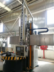
CNC milling is a machining process where a rotating multi-point cutting tool removes material from a workpiece. The workpiece usually stays fixed in position or moves slightly, while the cutter does most of the motion. By spinning at high speeds and following precise paths, the tool can shape surfaces, edges, and contours to match exact design requirements.
In a milling machine, the cutting tool can move in several directions. Common setups include 3-axis machines for standard vertical and horizontal cutting, 4-axis machines that allow rotation of the workpiece, and advanced 5-axis systems that tilt the tool or table for full access to complex shapes. It reads instructions from G-code, guiding the tool’s movements, depth of cut, and feed rate to create accurate parts.
Operators use face milling to create flat surfaces and square stock material. Slot milling cuts grooves or channels into the workpiece. Contouring shapes edges and angled surfaces, while pocketing removes material from interior sections to form cavities. Advanced techniques like helical milling form angled holes, thread milling produces internal or external threads, and gear cutting shapes tooth profiles for mechanical components.
Milling machines come in different configurations. Vertical mills position the spindle above the workpiece, offering flexibility for most tasks. Horizontal mills mount the spindle from the side, which is ideal for heavier or deeper cuts. Universal mills combine both orientations, giving operators a wider range of movement and machining possibilities.
Milling works with a variety of materials. Aluminum is lightweight and easy to cut, making it popular for aerospace and consumer products. Steel offers strength and durability for automotive and industrial parts. Titanium combines strength with corrosion resistance, suited for aerospace and medical components. Plastics like ABS and composites are also milled, especially when weight reduction or insulation is needed.
It handles complex shapes and intricate details that other processes can’t match. The method works across many materials, offering flexibility for different industries. Precision and repeatability remain high, even for multi-surface parts, and multi-axis setups reduce the need for multiple fixtures or setups.
Milling setups can take more time to prepare, especially for intricate designs. Tooling costs are often higher than in simpler processes, and advanced machines need more floor space. Complex programming for multi-axis work also requires skilled operators and longer preparation before production begins.
CNC turning is a machining process where the workpiece rotates at high speed while a stationary single-point cutting tool removes material. It shapes parts by shaving away the surface layer as the workpiece spins, producing smooth and precise dimensions. The rotation creates continuous contact between the tool and the material, ideal for round profiles.
Turning is carried out on machines like standard lathes, advanced turning centers, and Swiss-type lathes for small, high-precision parts. The workpiece is held securely in a chuck or collet, which keeps it centered during rotation. For long production runs, bar feeders can push new stock into position automatically, allowing the process to continue without constant operator input.
Facing flattens the end of a rotating part, often as a preparation step. Boring enlarges or finishes internal holes with better concentricity. Threading creates screw threads inside or outside the part. Grooving forms narrow channels, while knurling presses patterns into the surface for grip or aesthetics. Parting-off separates the finished piece from the stock material. Many turning centers also use live tooling to perform drilling, tapping, or small milling tasks without moving the part to another machine.
Turning works best with round bar stock in metals like aluminum, steel, and brass. It can also handle plastics such as nylon or ABS, and certain composites, as long as the tool speed and feed rates are adjusted to prevent deformation.
It is fast and efficient for cylindrical parts that require consistent diameters. The process delivers excellent concentricity and smooth surface finishes, making it suitable for shafts, bushings, and pins. Automation options like bar feeders further reduce labor needs while increasing output.
It is limited to rotationally symmetrical shapes and cannot produce complex multi-faced features without additional machining. Large or irregular workpieces may not fit standard lathe capacities, and adding non-round details often requires secondary processes or specialized hybrid machines.
The main difference lies in what moves during cutting. In milling, the multi-point cutting tool rotates and moves across the stationary or slightly moving workpiece. In turning, the workpiece spins while a stationary single-point tool removes material. This reversal changes the way shapes are formed and how cutting forces act.
Milling uses tools with multiple cutting edges, such as end mills or face mills, to remove material from various directions. Turning relies on a single-point cutting tool that follows a precise path along the rotating part. Each tool type is designed to handle different geometries and material removal rates.
Milling involves intermittent cutting, where each tooth of the tool engages and disengages the material repeatedly. Turning offers continuous cutting since the tool maintains steady contact as the workpiece rotates. These differences affect surface patterns, tool wear, and heat buildup.
In milling, chips are usually short and discontinuous because each cutting edge removes a small section before exiting the material. Turning can produce continuous chips, fragmented chips, or a mix, depending on the material and tool geometry. Chip control is critical for both methods, but the strategies differ.
Turning is ideal for cylindrical, conical, or symmetrical parts such as shafts and bushings. Milling excels at prismatic components with flat surfaces, slots, or complex 3D contours. Multi-axis milling expands the range, allowing angled features and intricate shapes in a single setup.
Turning delivers exceptional roundness and concentricity on rotational parts. Milling provides accuracy across multiple planes, enabling complex features with tight tolerances. Each process can achieve fine surface finishes when tooling, feed rates, and speeds are optimized for the material.
Turning is often faster for high-volume production of identical cylindrical parts, especially with bar feeders and automated loading. Milling offers more flexibility for small batches or custom parts that require multiple features and orientations. Choosing the right process depends on the geometry and production goals.
Milling setups can be more involved, often needing fixtures or vises to hold the workpiece securely for multi-surface machining. Turning setups are usually simpler, involving chucking or collet clamping along the workpiece axis. However, complex turning operations with live tooling can narrow this gap.
Both milling and turning are subtractive machining methods where material is removed from a solid block to form the desired part. They depend on precise control of tool paths and cutting conditions, which are driven by computer numerical control systems. In both cases, the process starts with a digital design created in CAD software. That design is translated into G-code, which tells the machine exactly how to move the tool or workpiece.
Each process works with a wide range of materials, from metals like aluminum and steel to plastics and composites. They both use coolants to manage heat, prevent tool wear, and clear chips from the cutting area. This not only improves surface finish but also extends the life of the cutting tools.
After machining, parts from either process often go through similar post-processing steps. Deburring removes sharp edges or leftover material, while polishing enhances the finish for functional or visual quality. These steps ensure that parts are ready for assembly or final use.
| Factor | CNC Milling | CNC Turning |
|---|---|---|
| Operational principle | The cutting tool rotates while the workpiece stays fixed or moves slightly | The workpiece rotates while a stationary single-point tool removes material |
| Machine configuration & tooling | Uses vertical, horizontal, or multi-axis mills with a wide range of cutters | Uses lathes, turning centers, or Swiss-type lathes with single-point tools and turrets |
| Part geometry | Best for prismatic shapes, flat faces, slots, and complex contours | Ideal for cylindrical, conical, and symmetrical parts like shafts or bushings |
| Workholding & fixturing | Requires vises, clamps, or custom fixtures to secure the part | Uses chucks, collets, or centers to hold rotating stock securely |
| Speed, feed, depth of cut | Feed rates and speeds depend on cutter size, flute count, and step-over distance | Speed depends on workpiece diameter and material, with depth of cut set for roughing or finishing |
| Materials | Handles metals, plastics, and composites in plate or block form | Works best with round bar stock in metals, plastics, and certain composites |
| Tolerances | Excels in multi-plane accuracy and intricate feature control | Delivers exceptional roundness and concentricity on rotational parts |
| Surface finish | Step-over and toolpath strategy determine finish, suitable for flat or contoured surfaces | Continuous contact produces smooth finishes with spiral patterns |
| Types of operations | Includes face milling, slotting, pocketing, contouring, thread milling, and gear cutting | Includes facing, boring, threading, grooving, knurling, and parting-off |
| Production volume & throughput | Flexible for low to medium batches, especially with varied designs | Highly efficient for high-volume runs of identical round parts, especially with bar feeders |
Turning is most efficient when producing cylindrical or conical parts that demand high concentricity. It works well for shafts, bushings, and pins, especially when stock comes in round bars. Using bar feeders allows automated loading, so the machine can run long production cycles without constant supervision. This makes it a cost-effective choice for high-volume manufacturing where speed and repeatability matter.
Milling is the better option when a part has multiple faces, intricate features, or complex 3D contours. It handles prismatic shapes, deep pockets, and angled cuts in a single setup on multi-axis machines. Parts like housings, molds, and structural brackets benefit from the flexibility of milling, where you can cut on several planes without removing the workpiece from the fixture.
Hybrid mill-turn machines combine both processes in one platform, making them ideal for parts that mix cylindrical and prismatic features. They reduce the number of setups, which saves time and improves accuracy since the part stays in the same fixture. This is especially useful for components like flanged shafts or valve bodies, where both turning and milling features must be completed in one cycle.
CNC milling and CNC turning share automation, precision, and material versatility but differ in motion, tooling, and ideal part shapes. Milling excels at prismatic and complex geometries, while turning dominates cylindrical production. Choosing the right method depends on geometry, material, and production volume. Hybrid mill-turn machines offer both flexibility and efficiency. Always consult a CNC specialist before making your decision. If you have other needs, welcome to see more of our products.
A: Milling uses a rotating multi-point tool on a fixed workpiece, while turning spins the workpiece against a stationary single-point tool.
A: Yes, many components combine cylindrical and prismatic features, often requiring both processes or a hybrid mill-turn machine.
A: CNC turning is usually more efficient for high-volume cylindrical parts, especially when using bar feeders for automation.
A: Both processes work with metals, plastics, and composites, though turning favors round stock and milling suits block or plate stock.
A: Use it when a part has both rotational and multi-surface features, allowing you to finish it in one setup.