- All
- Product Name
- Product Keyword
- Product Model
- Product Summary
- Product Description
- Multi Field Search
Views: 0 Author: Site Editor Publish Time: 2026-09-03 Origin: Site


Surface finish problems on CNC lathes trace back to seven common causes: tool chatter from excessive overhang, progressive insert wear, spindle bearing condition, workpiece deflection, incorrect coolant delivery, overly aggressive feed rates, and worn machine geometry. As a CNC lathe manufacturer with 15 years of production experience, Starfish Ruhr Heavy Machinery Technology (Dalian) Co., Ltd sees these same issues across customer workshops worldwide. Five of the seven causes can be corrected by adjusting tooling parameters or maintenance routines.
Roughness (Ra) is not a single number you achieve by buying the right insert. It is the result of dozens of variables working together. The theoretical formula for surface roughness in turning is Ra equals the square of feed per revolution divided by eight times nose radius. That formula gives you a starting point, but real-world finish depends on everything between the insert edge and the finished surface: tool holder rigidity, spindle condition, coolant coverage, workpiece material, and machine geometry.
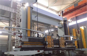
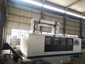
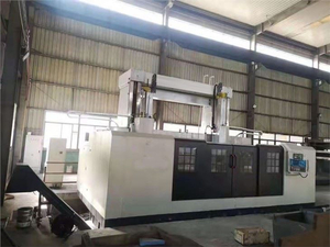
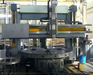
We test every CK5 vertical lathe and CK6 horizontal lathe with a standardized finish sample before shipment. If the machine cannot hold Ra 1.6 on 45# steel at our specified parameters, it does not leave the factory floor. Here are the seven problems we see most often when finish quality drops in the field.
Chatter marks show up as regular, wavy patterns on the workpiece surface, running perpendicular to the cutting direction. The most common cause is not the spindle, the material, or the insert. It is the tool sticking out too far.
When the cutting tool extends beyond the tool holder past a certain ratio, it acts like a diving board. The cutting forces push the tool tip, it deflects, springs back, and vibrates. Those vibrations print directly onto the workpiece.
We worked with a furniture manufacturing shop in Bogota, Colombia, that was getting visible chatter on oak table legs turned on a CK6150 horizontal lathe. The inserts were sharp and the spindle was fine. The problem was the overhang on their turning tools, which was nearly four times the tool holder diameter. We reduced the overhang from 80mm to 50mm, and the chatter disappeared immediately. Surface roughness dropped from Ra 3.2 to Ra 1.6.
The fix: Keep your tool overhang ratio at 3:1 (length to diameter) or less. For internal boring bars, use the shortest bar that clears the part. If you must reach deep, invest in vibration-dampened holders or anti-vibration boring bars with tungsten alloy cores.
Every insert cuts worse at hour 50 than at hour one. Flank wear builds gradually, the cutting edge rounds over, and instead of shearing the material cleanly, it starts rubbing and tearing. The surface gets rougher, but the change is slow enough that operators often do not notice until a customer rejects a batch.
In precision turning on a CK5 vertical lathe, a flank wear of just 0.3mm can double the Ra value. That is a jump from Ra 1.6 to Ra 3.2, invisible to the naked eye but obvious on a profilometer.
Our recommendation is to set tool life limits based on workpiece material. For cast iron, we typically see 200 to 300 parts per edge. For stainless steel, the number drops to 80 to 120. If you see roughness climbing mid-batch, do not wait for the scheduled tool change. Pull the insert and check the flank.
Another thing to watch: uneven wear patterns. If one side of the insert wears faster than the other, it usually points to a center height or alignment issue, not a bad insert batch.
When the finish has a regular pattern that does not match the feed marks or tool wear pattern, the spindle bearing is usually the cause. We had a customer in Texas running a large CK5 series vertical lathe for wind turbine components. The surface finish showed a repeating pattern every 0.8 seconds, roughly 75 marks per revolution.
The spindle bearing had developed slight play after years of heavy interrupted cuts on forgings. Even a radial movement of 0.01mm at the spindle nose transfers directly to the workpiece surface.
We check spindle runout with a dial indicator at the nose cone during annual maintenance. If the reading exceeds 0.005mm, we investigate further. For grease-lubricated bearings, we verify the grease interval and lubricant type. Over-greasing causes thermal expansion and preload loss. Under-greasing causes play. Both destroy surface finish.
When spindle replacement is needed, matching the original bearing preload specification is critical. A spindle rebuild with incorrect preload will produce poor finish regardless of everything else you fix.
When a long shaft bends under cutting pressure, the result is not just dimensional taper. The surface finish varies along the length because the actual depth of cut changes as the workpiece deflects and springs back.
On a CK6 horizontal lathe, the rule of thumb is to keep the length-to-diameter ratio below 10:1 without additional support. A customer in Surabaya, Indonesia, was machining 600mm stainless steel shafts at 60mm diameter on a CK6180. That is a 10:1 ratio, and they were getting visible taper plus roughness variation in the middle of the shaft.
Adding a steady rest at mid-length eliminated the taper, and the surface finish evenness improved from Ra 3.2 at the worst point to Ra 1.8 across the full length. The fix is straightforward:
Use steady rests or follow rests for workpieces exceeding 10:1 length-to-diameter ratio
For vertical lathe work, optimize the chuck jaw contact area to distribute clamping force
Consider using softer jaw materials (aluminum or polyurethane) for thin-walled parts
Reduce depth of cut on the finishing pass when the workpiece is likely to deflect
Coolant is not just about keeping things cool. It flushes chips away from the cutting zone, reduces friction between the insert and workpiece, and prevents built-up edge (BUE). When coolant is wrong, the wrong concentration, incorrect position, or insufficient flow, BUE forms on the cutting insert. That built-up material creates a new, unpredictable cutting edge geometry. It breaks off and reforms randomly, leaving a rough, inconsistent finish.
We once diagnosed a finish problem where the coolant pump was working fine, but the nozzle was positioned 150mm away from the cutting point. The coolant hit the workpiece behind the tool, not in the cutting zone. The insert was essentially running dry. Moving the nozzle to within 25mm of the cut solved it.
Coolant checklist:
Position nozzles within 25mm of the cutting point
Maintain coolant concentration at 5 to 10 percent for water-soluble coolants
Keep filters clean and replace them on schedule
For difficult materials like stainless steel or Inconel, use high-pressure through-tool coolant
On machines without high-pressure systems, use a focused stream rather than a flooded but unfocused approach
Feed rate is the single cutting parameter with the largest direct effect on surface finish. The theoretical formula shows this clearly: halving the feed should quarter the roughness. In practice, the relationship is not that clean because tool wear and vibration increase at very low feeds, but the direction is correct.
We had a customer in Ohio running a CK61125 horizontal lathe for heavy-duty shaft work. They were finishing at 0.4mm per revolution feed rate, producing Ra values around 6.3, which did not meet their specification of Ra 3.2. Dropping to 0.25mm per revolution on the finish pass brought them to Ra 2.8.
The approach is simple. Calculate the feed rate from the theoretical formula, set roughing passes for material removal rate, and reserve the reduced feed for the finishing pass only. If you need even better finish without sacrificing throughput, consider wiper inserts. They deliver one to two Ra grades improvement at the same feed rate by extending the contact length of the insert nose.
Over years of service, machines develop play in the ways, carriage gibs loosen, and tailstock alignment drifts. These geometric errors transfer directly to surface finish variation. On a vertical lathe, column squareness affects the flatness of faced surfaces. On a horizontal lathe, way wear creates taper.
As a CNC lathe manufacturer, we build our machines with precision-ground ways and preloaded linear guides. But even the best geometry degrades with 10 years of production. Our preventive maintenance program includes annual geometric checks on all customer machines still under service contract.
The fix is ongoing maintenance. Keep the gibs adjusted, the ways lubricated, and the ballscrews free from backlash. If your lathe is older and finish consistency has degraded, a way regrind or ball screw replacement can restore original accuracy at a fraction of the cost of a new machine.
Surface Finish Problem | Root Cause | Typical Fix |
|---|---|---|
Wavy chatter marks | Tool overhang too long | Reduce to 3:1 ratio or use anti-vibration holders |
Gradually increasing roughness | Insert flank wear | Set material-based tool life limits |
Regular repeating pattern | Spindle bearing condition | Check runout, verify preload, regrease or replace |
Taper and mid-length roughness | Workpiece deflection | Add steady rest, reduce finishing depth of cut |
Inconsistent rough finish | Built-up edge from coolant | Reposition nozzle within 25mm, check concentration |
Uniform roughness too high | Feed rate too aggressive | Reduce finishing feed or use wiper inserts |
Varying finish across workpiece | Machine geometry wear | Annual geometric maintenance, gib adjustment |
Surface finish problems are rarely caused by a single factor. More often, two or three small issues combine to push roughness past your specification. The fastest path to a fix is working through a systematic checklist rather than chasing individual symptoms.
Start with the insert. If it is worn or chipped, replace it before investigating anything else. Then check tool overhang. Then spindle runout. Then coolant flow. Then feed rate. Then workpiece rigidity. Then machine geometry. In our experience, fixing the first problem you find and re-testing saves more time than trying to address everything at once.
A properly maintained CNC lathe can achieve Ra 0.8 to Ra 1.6 on standard carbon steel with carbide inserts, and Ra 0.4 or better with CBN or diamond inserts on hardened materials. The achievable finish depends on insert nose radius, feed rate, material, and machine condition.
For finish-critical work, change inserts before they reach 0.2mm flank wear. On carbon steel, this typically means 150 to 250 parts per edge. On stainless steel, expect 60 to 100 parts. Set your tool life schedule around the workpiece material and required Ra value.
No. In our experience shipping CNC lathes to customers across the USA, Chile, Colombia, and Indonesia, roughly 70 percent of surface finish complaints are resolved by adjusting cutting parameters, tooling setup, or insert selection rather than repairing the machine.
Yes, but indirectly. Higher spindle speeds allow higher surface cutting speeds, which reduces built-up edge and improves finish on most materials. However, the dominant variables remain insert geometry, feed rate, and tool rigidity. Increasing speed alone will not fix a finish problem caused by excessive feed or worn bearings.