- All
- Product Name
- Product Keyword
- Product Model
- Product Summary
- Product Description
- Multi Field Search
Views: 0 Author: Site Editor Publish Time: 2026-09-13 Origin: Site


Thread cutting on a CNC lathe is done with a single-point insert that advances in a helix path while the machine locks the spindle rotation to the carriage feed, so pitch becomes a function of drive accuracy rather than operator skill. Vertical and horizontal lathe manufacturers such as Starfish Ruhr Heavy Machinery Technology (Dalian) Co., Ltd build CK5 vertical lathes with 800 mm to 16,000 mm swing and CK6 horizontal lathes that cut metric and inch thread forms to tolerance classes around 6g and 2A, exporting to more than 50 countries including the USA, Chile, Colombia, and Indonesia. Insert profile, pass count, and the finishing offset decide whether a thread meets gauge or becomes scrap.
Here is the part of threading that surprises most buyers. On a good CNC lathe the machine is rarely the reason a thread fails. We get at least one call a month from a customer whose threading cycle is producing galled, torn, or loose threads, and nine times out of ten the problem is in the insert, the pass schedule, or the way they measure, not in the axis drive.
A thread looks simple, but it is actually one of the hardest features a lathe makes. The tool has to cut a controlled helix with a specific profile, to a depth set by the pitch, without the insert chattering or the thread tearing as it exits. When a customer in Medellin first switched to one of our CK6 horizontal lathes, their very first batch of M42 coupling threads came off galled at the crest. The machine was cutting within tolerance on the test parts. The fix was entirely in how the passes were scheduled and how the last finishing pass was dressed.
On a manual lathe, threading depends on the operator engaging a half nut and hoping the spindle and lead screw stay in step. On a CNC lathe the control locks the spindle encoder to the Z axis feed, so the carriage advances exactly one lead for every single revolution. That is why a CNC machine holds thread pitch far tighter than even a careful manual operator, and it is why the same logic applies whether you cut a fine thread on a CK6 horizontal lathe turning a shaft or a coarse thread on a CK5 vertical lathe facing a large flange.
What the control does not do is correct a bad insert or a wrong offset. The pitch lead is set by the program, but the thread form you actually measure on the workpiece is set by the geometry of the cutting edge and by how deep each pass goes. That split, between what the machine guarantees and what the tooling decides, is the mental model our service engineers use every time they walk into a shop with a thread problem.
The insert has to match the thread form you are cutting, and this is where most confusion shows up. A standard metric thread is a 60 degree V form. An inch UN thread is also a 60 degree V, but the root radius and the flat at the crest are handled slightly differently than a metric thread. An Acme thread uses a 29 degree trapezoidal form, and a buttress thread is a very different shape again. A threading insert made for a 60 degree V form cannot produce a clean Acme thread, no matter how well the machine feeds it.
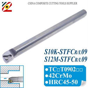
There are two broad insert families we explain to customers. A full profile insert cuts the complete thread form, including the crest, in one setup, which makes it the fastest way to get a thread that matches a go gauge. A partial profile insert, usually a 60 degree V, lets one insert cover a range of pitches because the tool sharpens the root and you cut the crest with a separate lead cutting operation. For production threads we usually steer customers toward full profile inserts because they remove the guesswork from the crest and the root radius.
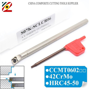
One detail that quietly causes scrap is the nose radius and the tool holder alignment. A threading insert has to be set square to the axis, with the centerline of the cutting edge at the workpiece center. If the insert rides high or low, the thread flanks cut at the wrong angle and the pitch diameter measures off even though the pitch is perfect. We check this on every machine before it leaves our factory, and we show the customer how to re-check it after a crash or a tool change.
This is the mistake that creates the most scrap, and it is also the easiest to fix. A threaded feature cuts a deep groove, and cutting the full depth in one pass overloads the edge, deflects the tool, and tears the flanks. The right approach is a series of passes that get shallower as the tool goes deeper, so the total cutting load spreads out and the flank finish stays clean.
For a 1.5 mm pitch thread, a schedule we use as a sensible starting point looks like this: about three rough passes of 0.3 to 0.4 mm depth, three intermediate passes of 0.2 to 0.25 mm, then two finishing passes at 0.05 and 0.025 mm. That sounds like a lot of passes, but on a CNC machine each one is fast, and the difference in thread quality is enormous. A customer in Santiago cutting hydraulic rod threads shaved their scrap almost to zero just by replacing a four pass schedule with a coordinated pass schedule that stepped down in depth.
The splash sheet on the machine panel is worth trusting here. Most controls write a suggested pass depth once you enter the pitch, and the numbers it suggests track the way metal removes best. If you override it and take one deep bite to save time, you usually lose the time twice when the thread tears and you redo the part.
The feature you actually have to hit is the pitch diameter, not the major diameter, and this is where a lot of shops trip up. The major diameter is easy to measure with a caliper, so people check that and call the thread good. The pitch diameter is what the gauge reacts to, and it sits partway down the flanks where a caliper cannot see it.
The reliable shop floor method for a single-point thread is the three wire method: three precision wires of the correct size for the pitch sit in the thread groove on opposite flanks, you measure over the wires with a micrometer, and you reference the reading against the pitch diameter formula in the thread standard. For critical threads we also keep a thread ring gauge or a plug gauge on hand, and a go no-go check is the fastest way to confirm the part will work with its mating component.
Our first-part rule is simple. We never let a production run of threads start until the first part has been measured with the three wire method or a gauge, not just a caliper. If the first part passes, the pass schedule and offset are saved, and the run stays in control. A customer in Houston that makes high pressure fittings learned this after a large lot came off with threads that looked fine and measured out of pitch diameter range. The calipers had lied because the major diameter was good.
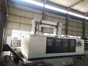
Thread cutting spans both configurations, and neither is better at everything. As a CNC lathe manufacturer that builds and services both, we see the split every week. On a horizontal lathe, like our CK6 horizontal lathes, threads on long shafts and through bores are natural because the tailstock supports the workpiece and the tool feeds along the full axis. Most standard bolts, rods, pipes, and hydraulic components fall here, and the between-centers rigidity keeps long threaded lengths from whipping at speed.
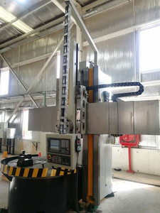
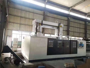
On a vertical lathe, large diameter threads on flanges, ring gears, and big heavy hubs are easier because gravity settles the part flat on the table and you face the thread in the direction gravity helps the chip clear. A customer in Indonesia cutting a coarse thread on a large mining flange found that moving the operation from a horizontal machine to one of our CK5 series vertical lathes steadied the cut and stopped the chatter they had battled, simply because the part now sat flat against the table.
As a CNC lathe manufacturer with fifteen years in the trade, those two situations are the pattern we see from our factory in Dalian across the four markets we serve: horizontal for the long, slender threaded work, vertical for the big, flat, heavy threaded work. Both Starfish Machine lathes carry the same spindle encoder and rigid feed, so both hold the pitch. The choice is about workpiece geometry more than threading capability.
Most thread failures come from the insert profile, the pass schedule, or measurement, not the machine. A wrong insert form, a cut taken too deep in one pass, or checking only the major diameter can produce scrap threads even when the control holds the pitch perfectly.
The three wire method over the pitch diameter is the reliable shop floor check, backed by a thread ring or plug gauge for critical features. Never rely on a caliper reading of the major diameter alone, because it does not show the pitch diameter the gauge reacts to.
Use a full profile insert when you need the complete thread form and crest with no extra operations, which is best for production. Use a partial profile 60 degree insert when you want one tool to cover a range of pitches and do not mind a separate crest operation.
Roughly six to eight passes for a typical 1.5 mm pitch thread, stepping down in depth so the load spreads and the flanks finish clean. Cutting a thread in one deep pass tears the flanks and usually costs more time in rework than it saves.
Yes. Both hold pitch the same way through the spindle encoder and feed lock. A horizontal lathe suits long shafts and through bores, while a vertical lathe handles large-diameter threads on flanges and heavy hubs where gravity helps the part settle and the chips clear.